WireFlow Test Framework
Fixtures
Modular fixtures make it possible to quickly create the perfect solution for every need.
State-of-the-art mechanics
By using high-quality materials, we ensure the reliability and accuracy of the test fixtures. We use only state-of-the-art fixtures from leading suppliers that we have worked with for decades.
To protect sensitive components against Electrostatic discharge (ESD) damage, we use ESD-compliant materials, with well-defined conductive properties in our test fixtures.
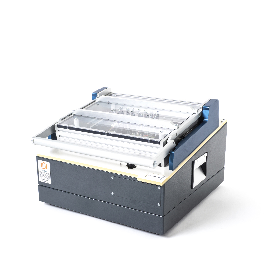
A medium size needle bed test fixture.
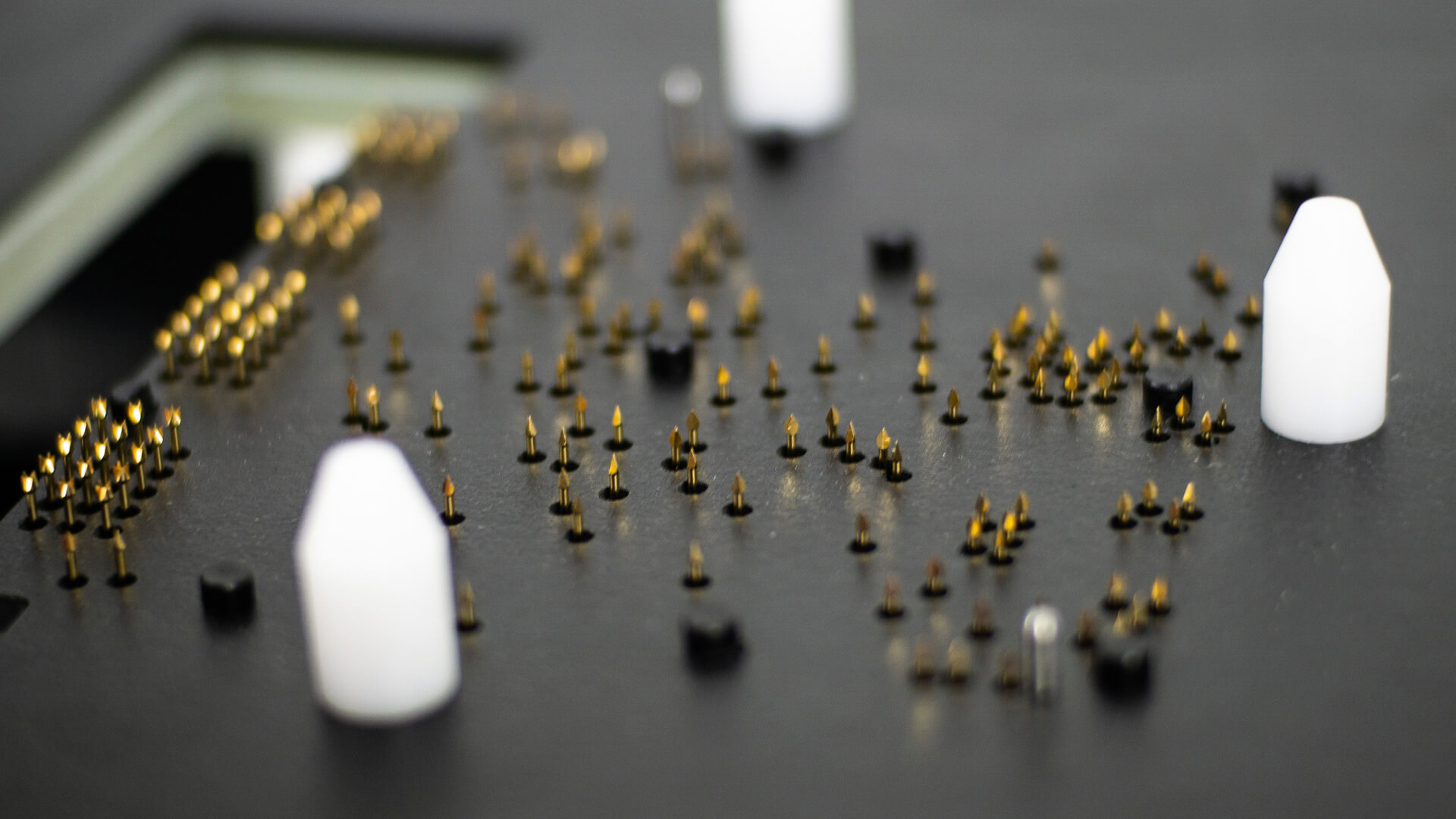
Spring-loaded test probes coming through the ESD-compliant plate.
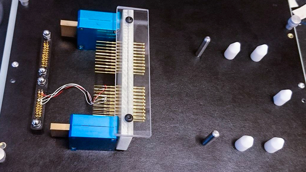
Side approach mechanism for attaching to a connector on the PCB.
For needle bed fixtures we use high-quality spring-loaded test probes that are manufactured with highest level of precision. The most common plunger materials are steel and BeCu, both of which are hardened. The springs retain their required contact pressure for several hundred thousand working strokes (test cycles).
The needles normally connect to the bottom of the circuit board but can also be made to connect from the top, or from the side if needed.
Inside an I/O box with instrumentation
Modular design with interchangeable cassettes
The WireFlow Test Framework offers a modular approach to fixture design, which is optimal in a variety of use cases. From the affordable fixture with minimal measurement I/O, to the high-volume needle bed fixture. When there is a need for testing many different variants of circuit boards, we recommend using our IO-box with interchangeable cassettes to lower the total cost of the solution. This concept enables re-use of the instrumentation for multiple variants of circuit boards.
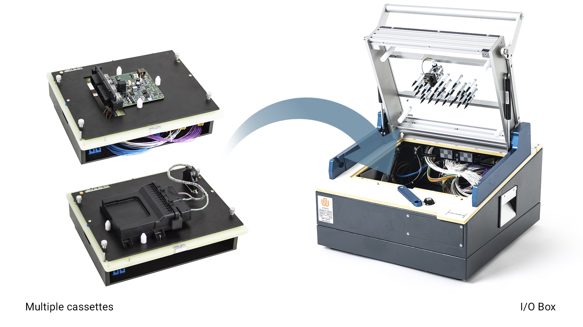
Fixture with interchangeable cassettes.
The concept of using cassettes provides an extra layer of wiring inside the cassette for increased flexibility. The cassette plate connects to the circuit board using a specially made needle bed or connector interface. The cassette contains wiring from the needles/connectors to the generic I/O-box connectors to which the instruments are connected. The wiring in the cassette can be made with wires of appropriate dimensions or can even be made with a customized PCB.
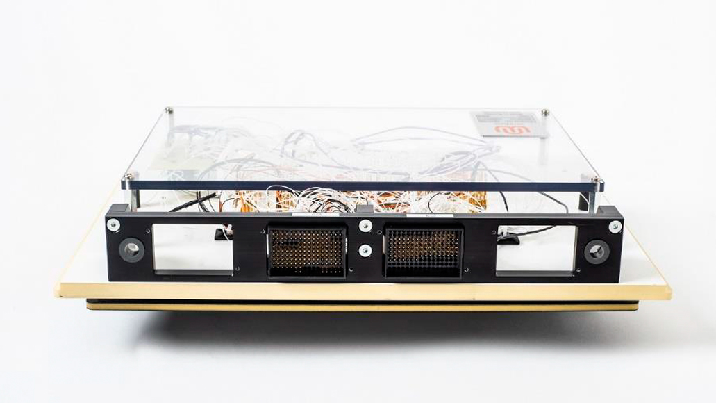
A needle bed cassette seen from back side and up-side down.
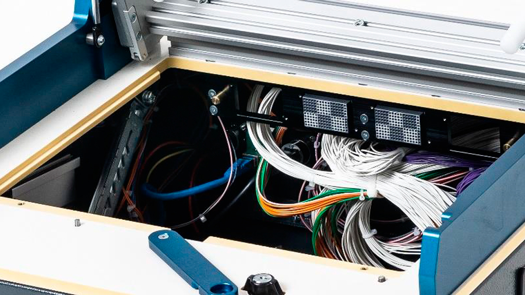
The cassette interface on the I/O-box.
In the photo above (5) we can see the back side of the cassette. It is these two connectors that attach the cassette to the I/O-box. The photo (6) shows the two receptacle connectors on the I/O-box.
The cassette contains wiring from the two connectors to the needles that will connect to the board under test. The cassette can also contain load resistors etc. that are necessary for the testing of this specific board.
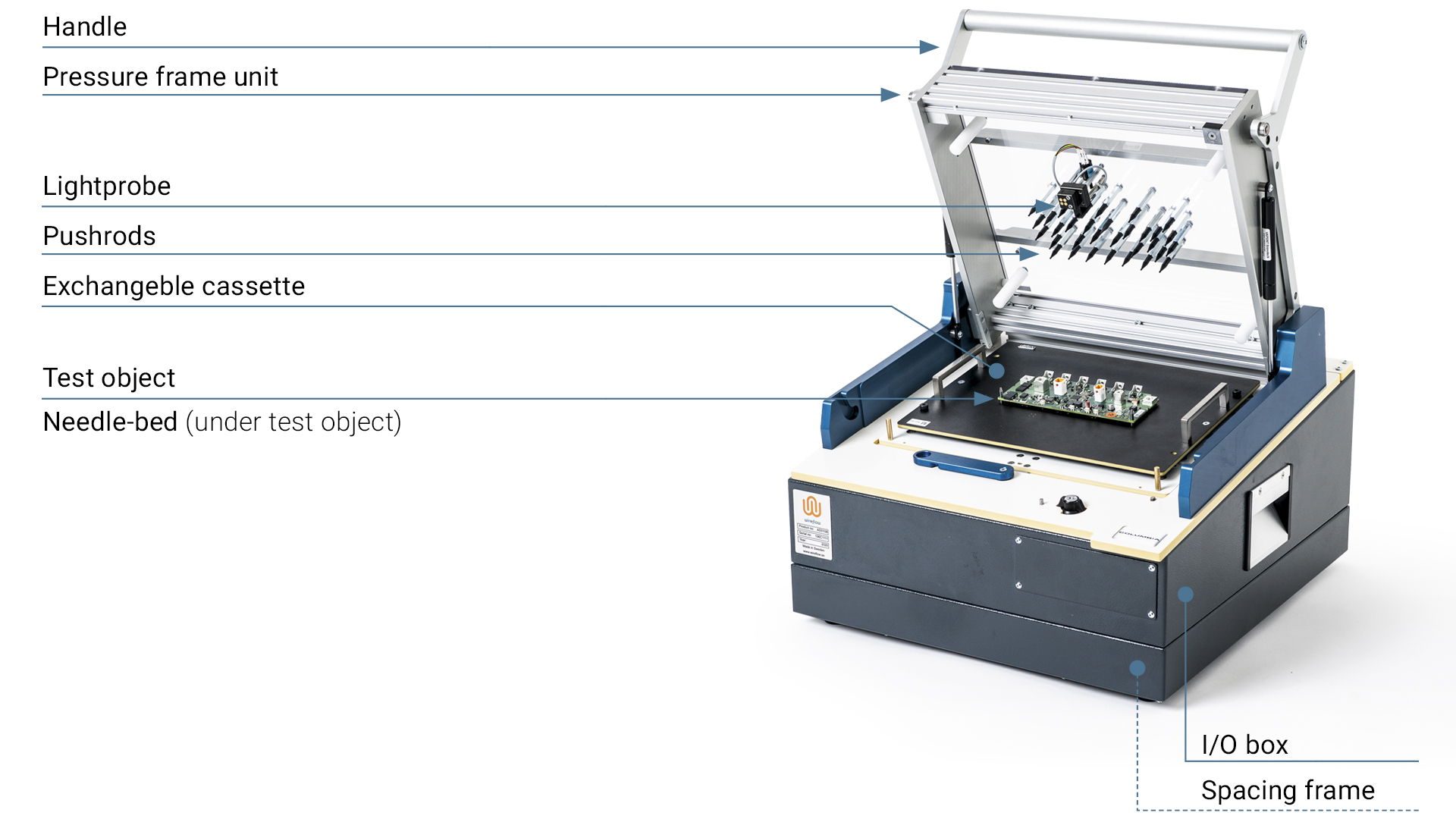
WireFlow has standardized the design of the fixtures and can offer them in several sizes. The fixtures are available with or without the cassette interface solution. If the box shall be equipped with instrumentation that requires extra space, a spacing frame can be added for extra height.

Fixtures of different sizes (small and mid-size)
Pushrods fixating the board
Connector and needlebed fixtures
A needle bed fixture is optimal for high volume production and is also required for boards with testpoints on the PCB. A PCB for needle bed testing must have guiding holes in the PCB that is used when placing the board on the fixture plate. The plate also has board-guides to ensure correct positioning. After the board is placed on the fixture the operator will close the pressure frame unit using the handle. Now pushrods will press the board against the fixture plate which will be lowered, and the needles will come up and connect to the test points on the PCB.
The sequence for attaching the board to the test equipment:
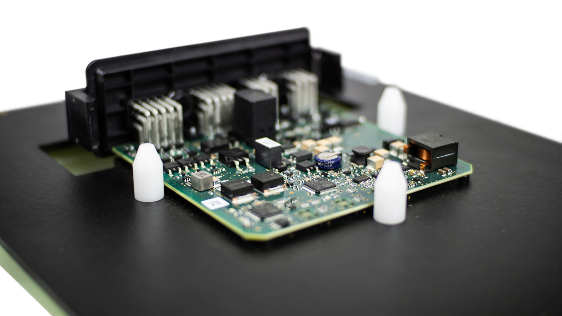
1. The board is placed in correct position on the plate by the board guides.
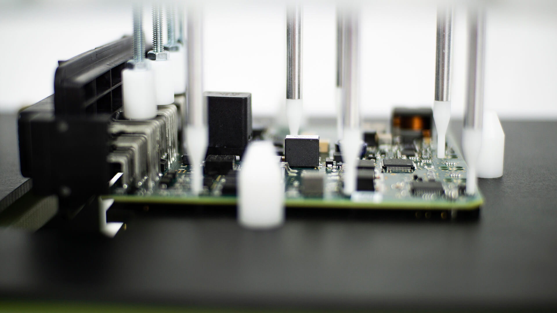
2. The pressure frame is closed and the pushrods are fixating the board.

3. The plate is lowered which makes the needles come up and connect to the board.
A more affordable alternative to a needle bed is to use connector interfaces. With this setup the board will be tested by accessing the signals normally found on the external connectors on the board under test. This is an appropriate solution for low volume production, and when there is no need to access internal testpoints on the board.
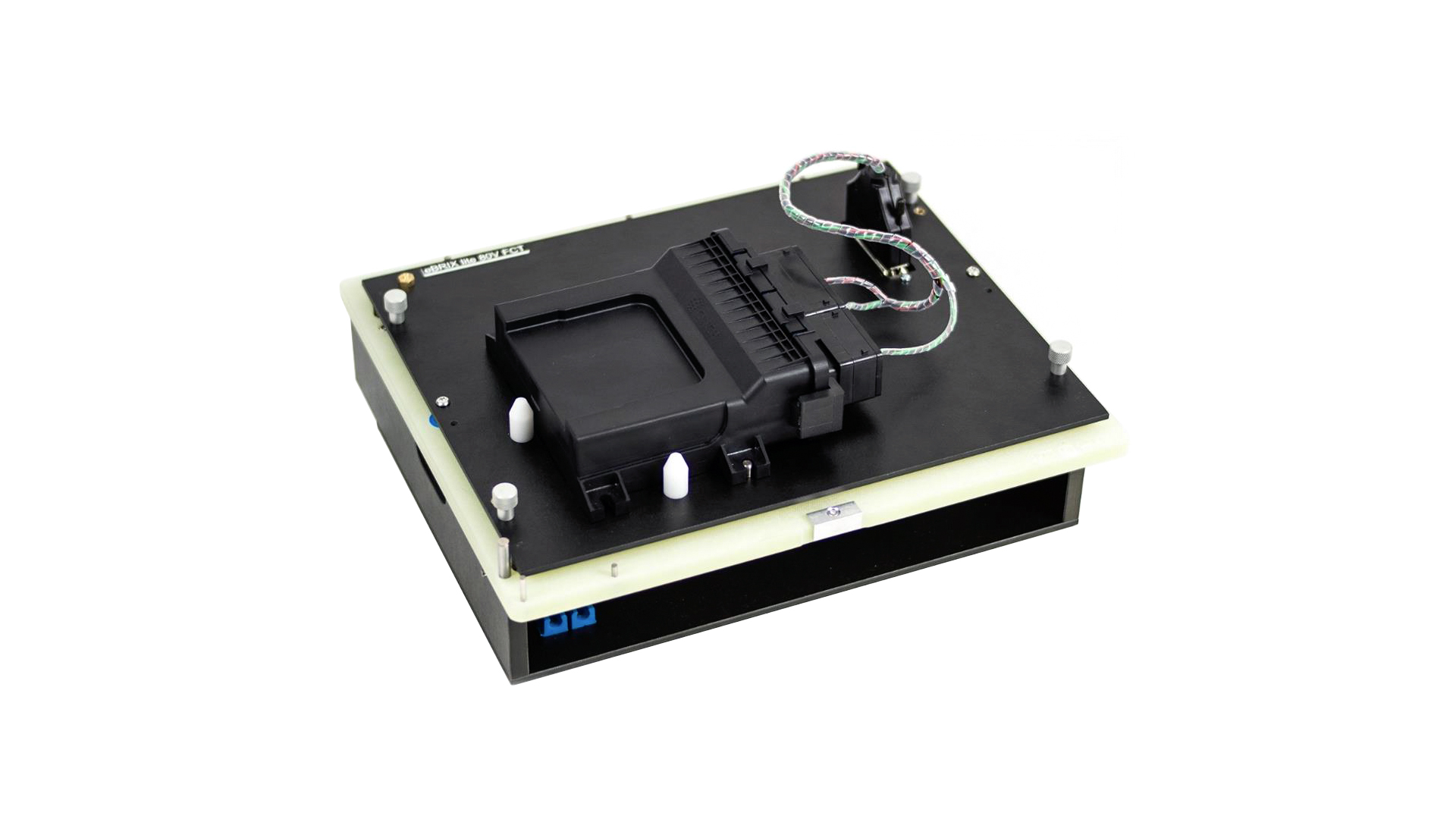
Cassette with connector interface.
With this setup it is possible to re-use the test fixture with many variants of boards. We just need to create a unique cable harness for each variant of board to test.
One drawback with the connector interface is that it is usually not possible to connect to any test points on the PCB, making it difficult to use In Circuit Test (ICT) methodology. Normally, it is only possible to use the Functional test methodology in this case.
If there is a need to access internal test points, but an affordable connector interface fixture is desirable, then WireFlow has an innovative solution also for this. By using a pre-defined footprint for the PCB layout, we can access these test points via a handheld connector that only attaches to the test points during testing and programming.
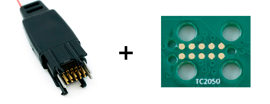
Solution for accessing test points with a connector interface fixture.
The I/O-box is configured according to your needs.
Flexible configuration of instrumentation
The instrumentation is placed in the I/O-box part of the test fixture. The choice of which types of instruments used depends upon the boards being tested. They can be power supplies, network devices, voltage meters, electronic loads, relays, communication bus interfaces etc.
WireFlow has a wide portfolio of well-proven instrumentation that can be used. By using these “standard” instruments we can reduce the development time since we already know how to mount and use the instruments. We also have ready-to-use software drivers for these instruments.
The I/O-box is configured according to your needs. Beside the “standard” instruments, it is common that the box is also equipped with special instruments and other devices that are needed to test your specific board. We do this customization with ease due to the flexibility and scalability of the platform.
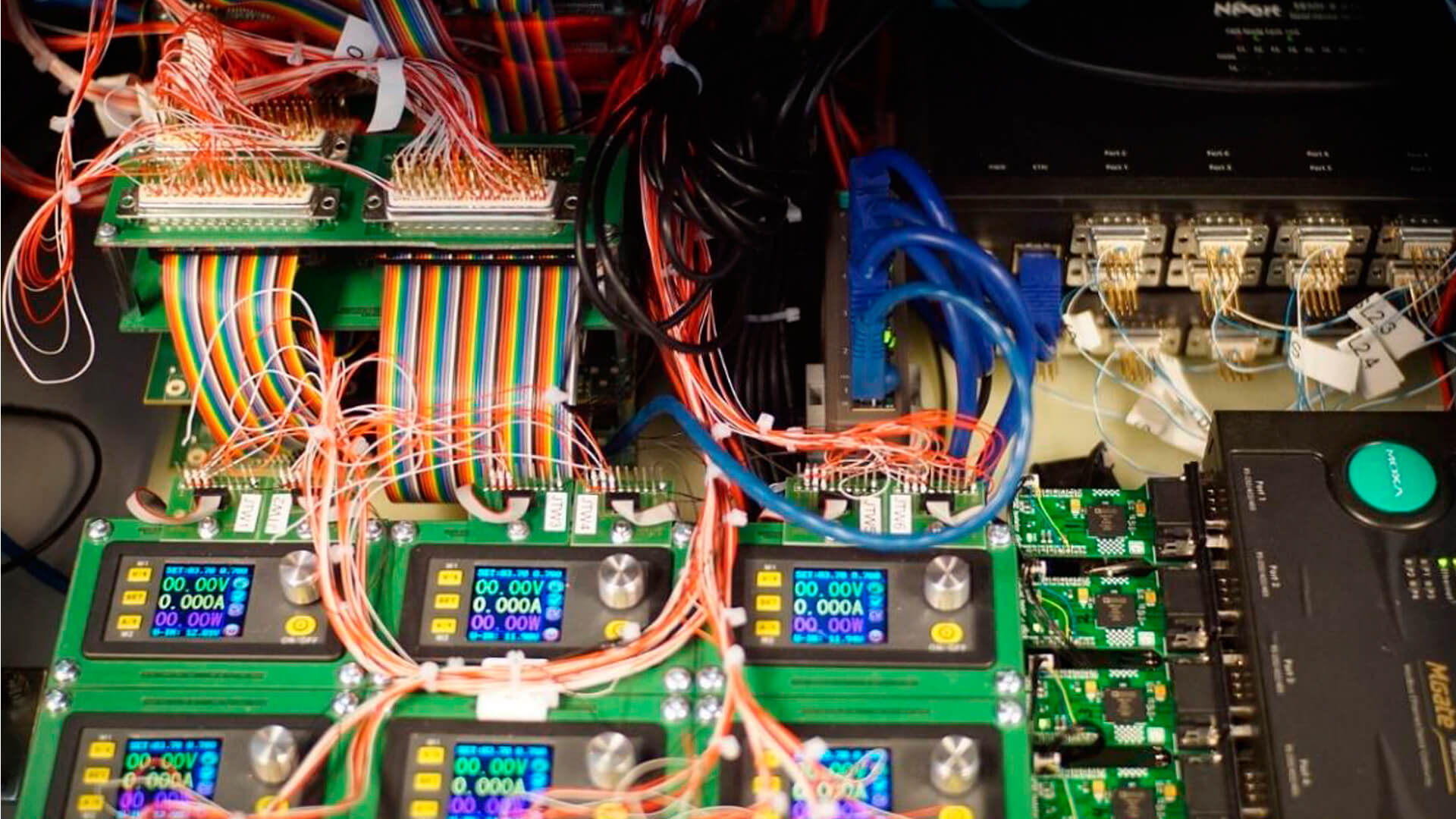
An I/O -box with instrumentation
About WireFlow Test Framework
WireFlow has long experience in helping companies set up test and programming environments for electronic production. We have gathered all our tools and knowledge into a versatile framework we call WireFlow Test Framework. Using our framework, we can help you to quickly develop an effective and affordable solution for testing and programming your products in the production line.
Take a look at any of the other fundamentals of WireFlow Test Framework:
